INTRODUCTIONWireless USB is an asynchronous Wireless standard which supports a high data transfer rate up to 480Mbps. WUSB Host-Device communication is based on DRP (Distributed Reservation Protocol) for TDMA type data communication. So Host gives the instructions to device along with the ‘time’ when that instruction has to be performed, such as transmission or reception. So in order to follow the timings of all the timing crucial instructions there should be synchronization between device and the host. DETAILS ABOUT MMCsWireless USB defines a Wireless USB Channel which is encapsulated within a set of MAC Layer MAS reservations. The Wireless USB Channel is continuous sequence of linked application-specific control packets, called MMCs (Micro-scheduled Management Commands), which are transmitted by the host. MMCs contain time reference to the next MMC in the sequence. These links provide a continuous thread of control which can be simply followed by devices that join the Wireless USB Cluster. This encapsulated channel provides the structure that serves as the transmission path for data communication between a host and devices in a Wireless USB Cluster. The linked stream of MMCs is used primarily to dynamically schedule channel time for data communications between host applications and WUSB endpoints. An MMC specifies the sequence of micro scheduled channel time allocations (MS-CTAs) up to the next MMC within a reservation instance. It can be followed by another MMC without the existence of MS-CTAs between two MMCs in which the MMC is only used to convey command and control information.
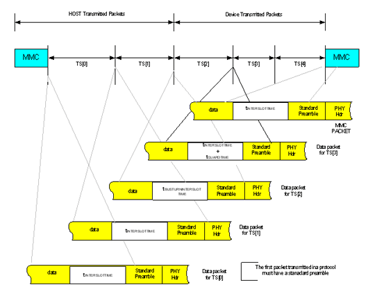
TRANSACTION GROUP TIMINGThe host orders individual transactions within transaction groups to minimize the number of ‘bus turns’ (e.g. turning the host’s radio from Transmit to Receive). A transaction group is constructed to have all the host Transmit protocol time slots immediately after the MMC, followed by a ‘bus turn’ and then all Device Transmit protocol time slots. Note there is another ‘bus turn’ between the last Device Transmit time slot and the next scheduled MMC packet.
The first two protocol time slots indicate OUT (host to device) transmissions. Protocol time slots in a transaction group must be ordered OUT then INs, so the host is the transmitter of all the packets beginning from an MMC until the first IN protocol time slot. This looks in many respects like a burst transfer (supported in many PHY standards), although the recipient devices in adjacent protocol slots may be different for this application. For adjacent OUT protocol time slots, the minimum inter-slot time must be tINTERSLOTTIME. There is no need to add guard times between these consecutive OUT transactions (or between the MMC and the first OUT,) since the host is the transmitter of all these packets. The receiving device, however, must start listening at least a calculated guard time (tGUARDTIME) before the anticipated packet start time. During device to host (IN) transactions, the minimum inter-slot time between successive IN transactions must be tINTERSLOTTIME plus tGUARDTIME since the IN time slots could potentially be used by different transmitters with drifting clocks. When an MMC or OUT protocol time slot is followed by an IN protocol time slot, or an IN protocol time slot is followed by an MMC, then the minimum inter-slot time must be equal to the calculated guard time (tGUARDTIME) plus the host’s bus switch time (tBUSTURNTIME) which is a PHY-related timing parameter. The sum of these is the bus turn inter-slot time (tBUSTURNINTERSLOTTIME).The final components in calculating protocol slot time durations are the inter-packet gaps and size of preambles between packets in slots where multiple packets are transmitted. PHY standards may (or may not) define a minimum and maximum value for burst-mode inter-packet gaps and the use of streaming preambles (which can be shorter than standard preambles). When necessary, Wireless USB does define a maximum requirement for the streaming mode inter-packet gaps. The availability of streaming preambles is also a PHY-specific parameter. PROTOCOL SYNCHRONIZATIONAll Wireless USB Protocol timings are specified relative to the beginning of the preamble for the MMC packets.
The ‘end of list’ WXCTA must be the last WXCTA block in a WCTA_IE. The ‘end of list’ WXCTA block must not be interpreted as a WXCTA for use with a valid Function Endpoint. In the case were the last WXCTA before the EOL WXCTA is a WDRCTA then the next MMC time must be at least a calculated guard time (tGUARDTIME) larger than the wStart value of the EOL WXCTA. In the case of a WDTCTA before the EOL WXCTA, the next MMC time must be at least tBUSTURNTIME + tGUARDTIME larger than the wStart value of the EOL WXCTA. Note that larger in this context must accommodate appropriately for channel time rollover conditions. ARCHITECTURE
Timing Handover Mechanism Between different Counters:Timing Hand over Technique But the adder specially to add Pclk means increasing hardware, so there is one possible solution to this problem. Technique to reduce the hardware by avoiding the adders This method avoids adders specially for adding residual Pclk values. CONCLUSIONWith the help of Device Timer block design can achieve Protocol Timing synchronization and also reduction in the complexity and thus the hardware of other blocks because all the timing enables generations are dedicated to this block, which further makes a ease of debugging the design. |
Feedback |
| If you have any suggestion/feedback please email it to [email protected] |

